ATmega8 Timer1 Fast PWM
Dieses Programm erzeugt im Fast PWM Mode zwei PWM Signale
|
Beschreibung Dieses Beipsiel für den ATmega8 Timer1 PWM läuft im fast PWM Mode. Die zwei Ausgänge PB1 und PB2 liefern 2 PWM Signale, deren duty cycle über die Register OCR1A und OCR1B eingestellt werden können. Derr PWM läuft mit 8 Bit und einem Timer1 Prescaler von 1024. |
Please visit: the four
|

C Sourcecode
#include <avr/io.h>
int main(void)
{
DDRB = 0x06; // Set Port PB1 and PB2 as Output
TCCR1A = (1<<WGM10)|(1<<COM1A1) // Set up the two Control registers of Timer1.
|(1<<COM1B1); // Wave Form Generation is Fast PWM 8 Bit,
TCCR1B = (1<<WGM12)|(1<<CS12) // OC1A and OC1B are cleared on compare match
|(1<<CS10); // and set at BOTTOM. Clock Prescaler is 1024.
OCR1A = 63; // Dutycycle of OC1A = 25%
OCR1B = 127; // Dutycycle of OC1B = 50%
for(;;); // Endless loop;
// main() will never be left
return 0; // This line will never be executed
}
Download C-Sourcefile mit ASCII-Schema: C-Sourcefile mit ACII-Schema
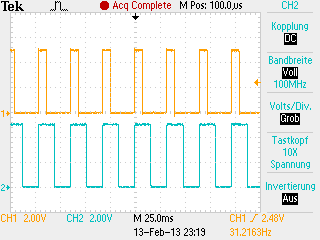
Signalplots
|
|
Gelb: Digitaler Ausgang OC1A
|