ATmega16 ADC mit Interrupt
Dieses Codebeispiel zeigt, wie man auf dem ATmega16 einen Interrupt nach der ADC Wandlung auslöst.
|
Beschreibung Der ADC wird im single conversion Modus betrieben. Jeses mal wenn eine Wandlung abgeschlossen ist, wird der ADC Interrupt ausgelöst. In der Interruptroutine wird die nächste Single Conversion gestartet. Während der Wandlung wird das Mainprogramm ausgeführt. Dieses lässt einfach den Ausgang PB1 toggeln um zu demonstrieren, dass das Hauptprogramm trotz der ADC Wandlung läuft. Die Interruptroutine setzt den ausgang PB0, wenn der ADC Wert grösser als 512 ist auf true. Ausserdem zeigt die Interruptroutine mit dem Port PB2 an, ob sie gerade läuft oder nicht. |
Please visit: the four
|

#include <avr/io.h>
#include <avr/interrupt.h>
int main(void)
{
DDRB = 0x07; // Setup PB0, PB1 and PB2 as output
ADMUX |= (1<<REFS0)|(1<<MUX2); // Set Reference to AVCC and input to ADC4
ADCSRA |= (1<<ADEN)|(1<<ADPS2) // Enable ADC, set prescaler to 16
|(1<<ADIE); // Fadc=Fcpu/prescaler=1000000/16=62.5kHz
// Fadc should be between 50kHz and 200kHz
// Enable ADC conversion complete interrupt
sei(); // Set the I-bit in SREG
ADCSRA |= (1<<ADSC); // Start the first conversion
PORTB |= 0x04; // Indicate the start of the conversion
for(;;) // Endless loop;
{
PORTB^= 0x02; // Toggle PB1
} // main() will never be left
return 0; // This line will never be executed
}
// Interrupt subroutine for ADC conversion complete interrupt
ISR(ADC_vect)
{
PORTB &= ~0x04; // Indicate the end of the conversion
if(ADC >= 512) // Compare the conversionresult with 512
PORTB |= 0x01; // If larger, set PB0
else
PORTB &= ~0x01; // If smaller, reset PB0
ADCSRA |= (1<<ADSC); // Start the next conversion
PORTB |= 0x04; // Indicate the start of the conversion
}
Download C-Sourcefile mit ASCII-Schema: C-Sourcefile mit ACII-Schema
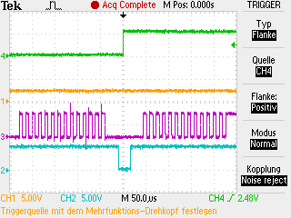
Signalplots
|
|
Gelb: Analoges Eingangssignal PA4
|
|
|
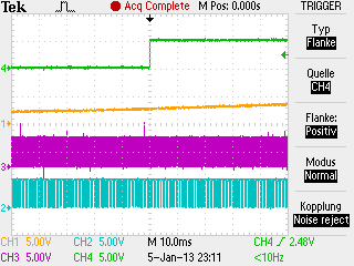
Gelb: Analoges Eingangssignal PA4
|