
Diode in forward and reverse bias
Here you find the basic circuits for the diode in reverse direction and in forward direction.
We will look at the basic circuits for forward and reverse operation and have a look on calculation examples.
VD und ID in forward and reverse bias
The diode is the one-way street for electrons. In forward direction current can flow,
in reverse direction no current flows. But this is only half the truth. Also in reverse direction
a very small current flows. But it is so small that it can be ignored in most cases.
The voltage VD drops across the current ID flows trough the diode. Depending on whether the diode is operated in forward direction or not, sometimes other terms are used for VD and ID:
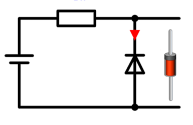
Figure 1 shows the diode in the forward and the reverse mode.
The voltage VD drops across the current ID flows trough the diode. Depending on whether the diode is operated in forward direction or not, sometimes other terms are used for VD and ID:
- VForward und IForward, wenn the diode is forward biased.
- VReverse und IReverse, wenn the diode is reverse biased.
- VD und ID, can be used for both operating modes. It is positive in forward direction and negative in reverse direction.
Figure 1 shows the diode in the forward and the reverse mode.
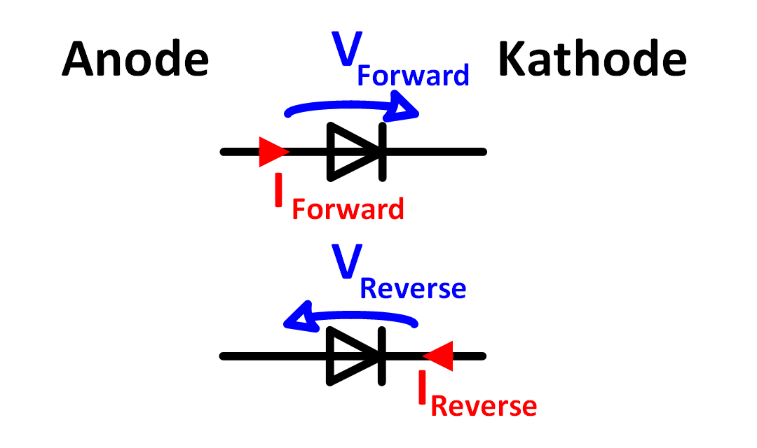
Figure 1: Diode Anode, Cathode Forward Current und Reverse Current
The different terms for forward and reverse operation are used e.g. in the diode datasheets
to describe the component characteristics in the two different operating modes.
Basic circuit of the forward biased diode
Figure 2 shows the diode in forward direction. The anode is connected to the positive
voltage and the cathode is connected to the negative voltage. The diode current flows in the
same direction as the arrow of the diode symbol and on the diode drops the forward voltage
VD or VForward. It is about 0.7V. The other part of the source voltage
drops as VR on the series resistor.
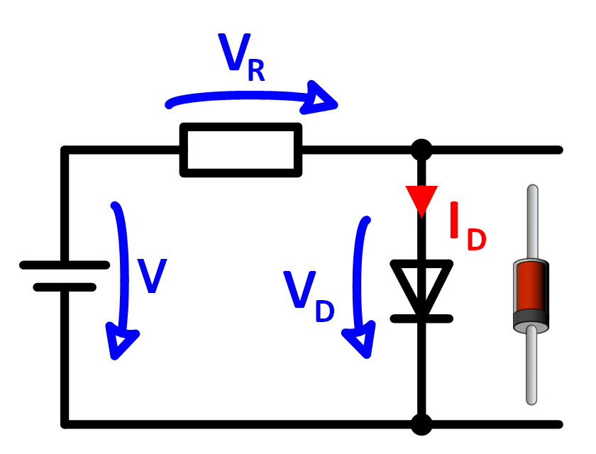
Figure 2: Diode in forward bias
Basic circuit of the reverse biased diode
Figure 3 shows the diode in reverse direction. The cathode is connected to the positive
voltage and the anode is connected to the negative voltage. The diode current flows against the
arrow of the diode symbol. The diode is blocking and only the very small reverse current IReverse flows.
Virtually all of the source voltage drops on the diode and appears as VReverse.
Virtually no voltage drops on the resistor.
Virtually all of the source voltage drops on the diode and appears as VReverse.
Virtually no voltage drops on the resistor.
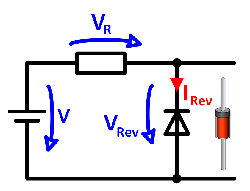
Figure 3: Diode in reverse bias
Calculation example for diode in forward direction
The calculation example in Figure 4 shows how to calculate the diode current and the voltage of the series resistor when a diode is operated in forward direction.
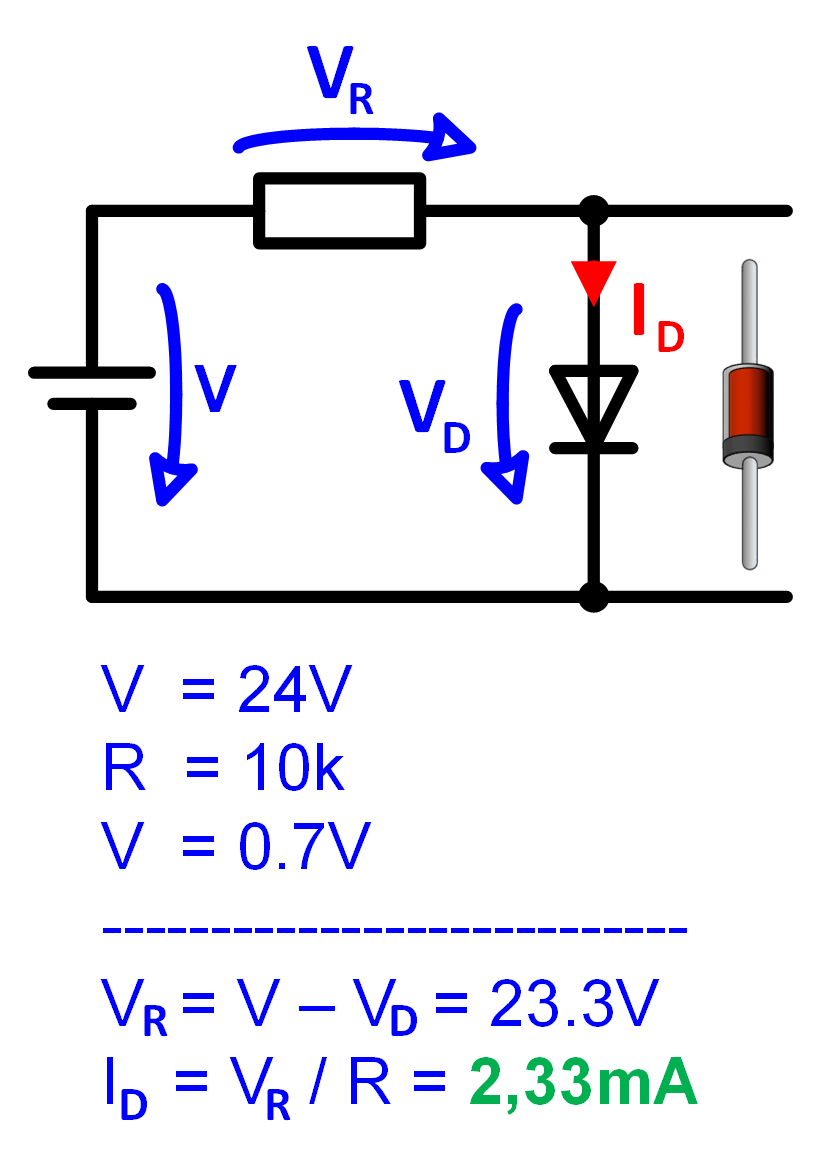
Figure 4: Example forward bias
A diode and a resistor of 10k are connected to a DC voltage of 24V. The diode voltage
is 0.7V in this case. 23.3V drop on the resistor. The current can be calculated with the
resistor voltage and the resistance according to Ohm's law.
Calculation example for diode in reverse direction
The calculation example in Figure 5 shows how to calculate the diode current and the voltage at the series resistor in the reverse direction.
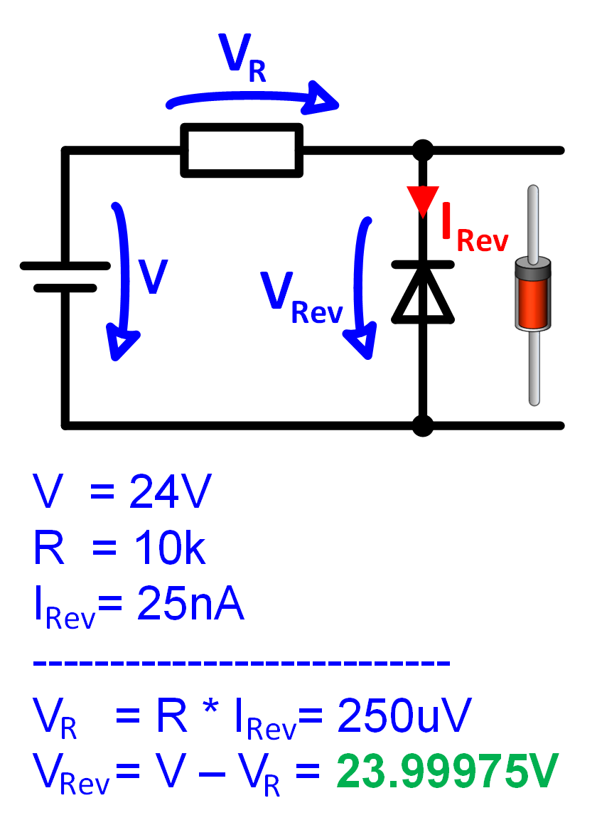
Figure 5: Example reverse bias
A diode in reverse direction and a resistor of 10k are connected to a DC voltage of 24V.
The diode current is almost independent of the voltage and is always 25nA. From the current and
the resistor you can calculate the very small voltage across the resistor. The voltage across
of the diode results from the subtraction of the resistor voltage from the input voltage.
X
Figure 1: Diode Anode, Cathode Forward Current und Reverse Current
Figure 1: Diode Anode, Cathode Forward Current und Reverse Current
X
Figure 2: Diode in forward bias
Figure 2: Diode in forward bias
X
Figure 3: Diode in reverse bias
Figure 3: Diode in reverse bias
X
Figure 4: Example forward bias
Figure 4: Example forward bias
X
Figure 5: Example reverse bias
Figure 5: Example reverse bias