
Diode and resistor in series
A diode needs a resistor in series to limit the current. Without it it is hardly possible to
adjust the current through the diode in a way the diode can be operated correctly. In this article
we show how the diode and the resistor behave together and how their characteristic curves
interact with each other .
The characteristics of a standard diode
Let us first look at the diode without the resistor in series. Diodes in SMD and through-hole mount look like shown
in picture 1. Usually a diode has a line mark on one side, which indicates where the cathode is located. The symbol
of the diode also has a dash that marks the cathode. The arrow direction of the symbol indicates the direction in
which the diode lets the current pass: From the anode to the cathode.
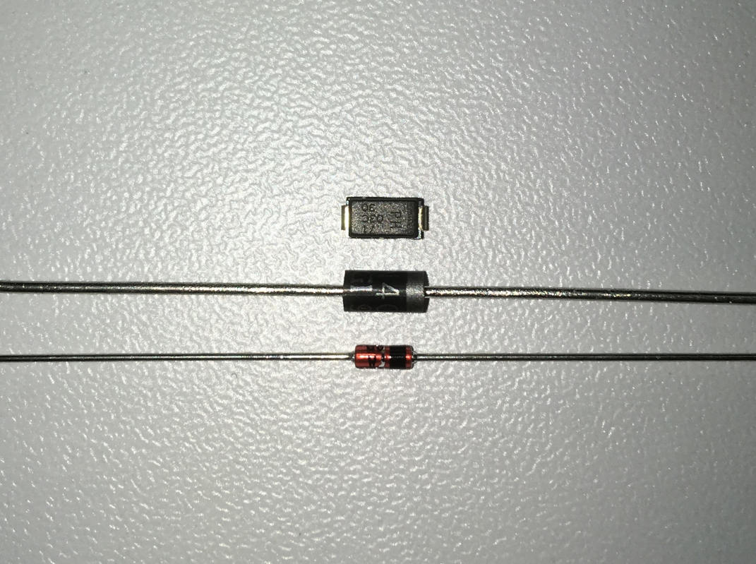
Figure 1: Variants of diode housings
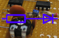
Figure two shows the symbol of the diode on a voltage source.
The voltage VD drops across the diode and the current ID flows through the diode.
It is not recommended to operate a diode in this way. Diodes should always be combined with a series resistor.
But we will now look at how a diode reacts when operated in series without a resistor in the next sections. From this we will see what advantages an additional resistor brings.
It is not recommended to operate a diode in this way. Diodes should always be combined with a series resistor.
But we will now look at how a diode reacts when operated in series without a resistor in the next sections. From this we will see what advantages an additional resistor brings.
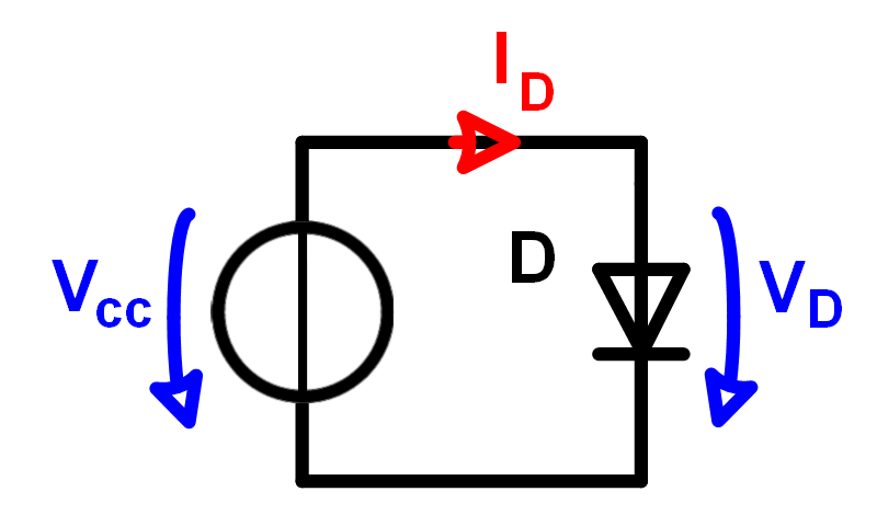
Figure 2: Diode curve
Figure 3 shows a diode characteristic curve. Characteristic curves are the best way to describe the
function of a component. The characteristic curve of the diode shows the relationship between current
and voltage. E.g. that a current of 100mA can flow through the diode when 0.7V drops on it. If only
0.1V drops across the diode the diode current is 0mA and at 2V it's 2A.
We see that a voltage change below 0.55V has practically no influence on the current. Above 0.7V the current increases very much at a small voltage increase.
We see that a voltage change below 0.55V has practically no influence on the current. Above 0.7V the current increases very much at a small voltage increase.
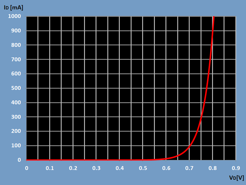
Figure 3: Diode on a voltage source without resistor in series
How to not exeeding the diodes maximum current.
To understand the importance of the resistor, which we connect in series with the diode, we need
to know that each diode has a maximum allowable current. In the data sheet of the diode it is
usually found under "Absolute maximum ratings". It is defined e.g. like in figure 4. The diode
of this datasheet allows a maximum current of 300mA. This means, for this diode characteristic
curve, that we must take care that VD doesn't exceed 0.75V.

Figure 4: Absolute Max Ratings of a diode
If we want to operate the diode with the characteristic shown in figure 3 at e.g. 100mA, we need a voltage of exactly 0.7V. But if the voltage
increases only by 5%, to 0.735V, we already have a current of 200mA. Thise sensitivity is shown in figure 5.
In practice, however, it is hardly possible to set a voltage and current so precisely for the following reasons:
In practice, however, it is hardly possible to set a voltage and current so precisely for the following reasons:
- Voltage source deviation
- Temperature stability of the voltage source
- Unknown level of the voltage source (e.g. for batteries that have different charge levels)
- Deviation of the diode characteristic curve under different temperatures
- Diversity of the diode characteristic curve

Figure 5: Diode curve between 0.7V and 0.735V
A series resistor added to the diode keeps the current stable
To stabilize the current at the correct value, we connect a resistor to the diode in series,
which has a less sensitive characteristic curve and defines the current-voltage ratio in the series connection.
In this example the resistor has the linear characteristic of 33 Ohms like in Figure 6.
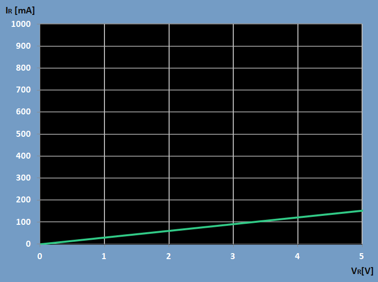
Figure 6: Resistor characteristic curve 33 ohm
Grafische Bestimmung des Stromes und von VR und VD
If this resistor is now connected in series to the diode, a very clear principle results:
Since the diode characteristic curve is exponential and the resistance characteristic curve is linear, a change in voltage will cause the major part of the voltage difference to act in the resistor, because the same current change must occur in both components.
- The same current flows through both components
- Both components split the supply voltage
Since the diode characteristic curve is exponential and the resistance characteristic curve is linear, a change in voltage will cause the major part of the voltage difference to act in the resistor, because the same current change must occur in both components.
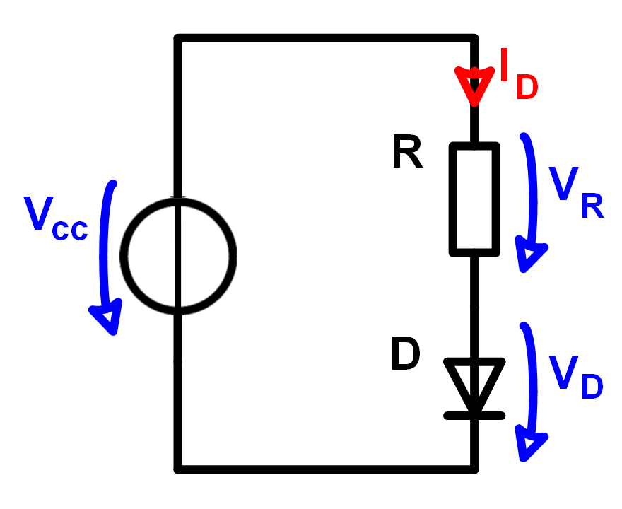
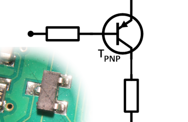
Figure 7: Diode with resistor in series circuit
For given VCC and R (in the following example Vcc = 5V and R = 33Ohm)
a formula for the diode current can be set up:
The diode current can not only be read from the diode characteristic curve, but it is also determined by the resistance and the supply voltage. Figure 8 shows the formula for this.
The diode current can not only be read from the diode characteristic curve, but it is also determined by the resistance and the supply voltage. Figure 8 shows the formula for this.
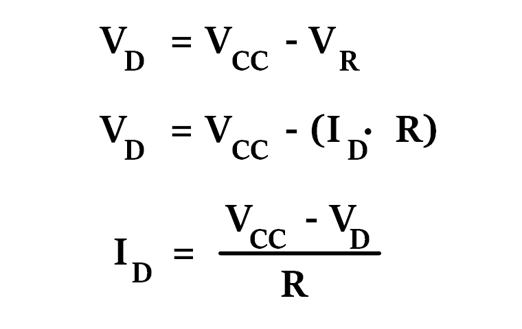
Figure 8: Diode voltage and current @ fixed Vcc and R
This formula for ID is linear. Therefore we can use any value for VD
and determine a straight line from the VD,ID-pairs computed from them.
This straight line shows how the diode current behaves when the diode is connected to Vcc
and R.
In figure 9 we calculate ID for the more theoretical diode voltages of VD = 0 and VD = Vcc
In figure 9 we calculate ID for the more theoretical diode voltages of VD = 0 and VD = Vcc
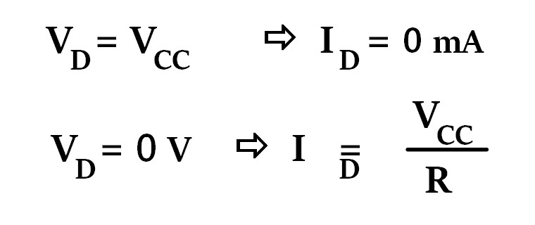
Figure 9: Two points on the linear function
In Figure 10 we create a linear function from the more theoretical extreme values of Figure 9.
This function describes the diode current dependent
of Vcc and R.
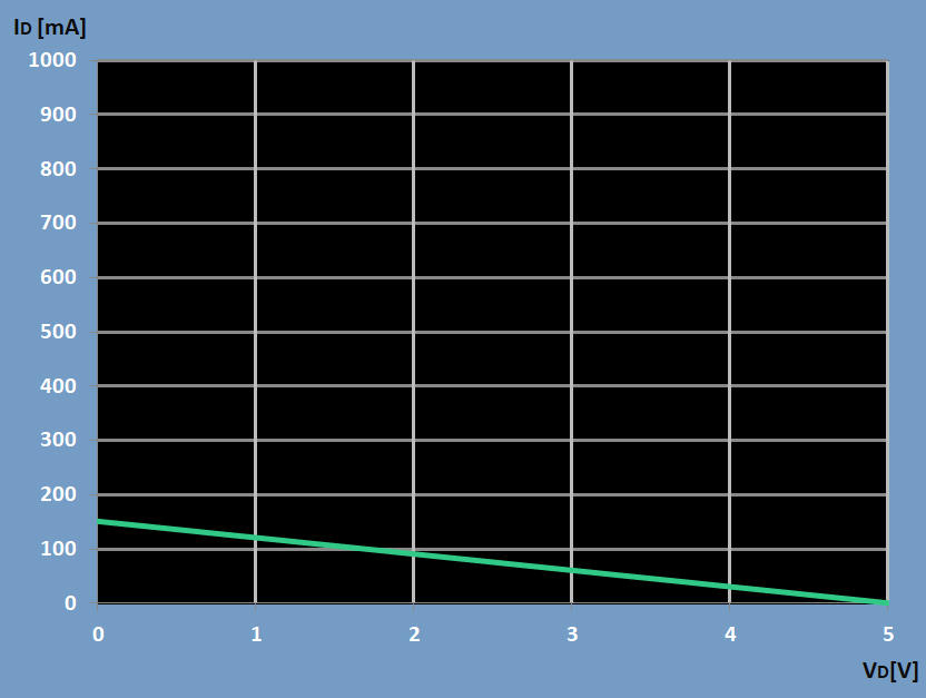
Figure 10: ID @ given Vcc and R
Both characteristic curves of figure 5 and 10 describe the diode current in dependence of the diode voltage
The point of intersection of both curves is the point where both have the same current ID and the same
diode voltage VD. This point is the operating point of the diode. Fig. 11
combines the two curves and Figure 12 shows the enlarged zoom of the intersection.
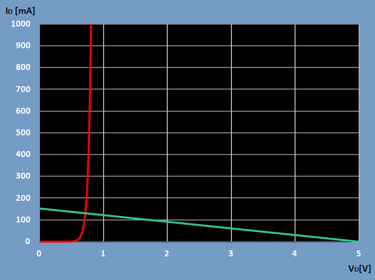
Figure 11: Interception point of the characteristic curves of the resistor and the diode
From Figure 12 we can read VD and ID. If the diode is connected to a resistor of 33 Ohm in
series and Vcc is 5V, a current of 130mA flows through the diode and VD is 0.72V.
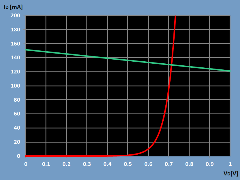
Figure 12: Zoom on interception point
X
Figure 1: Variants of diode housings
Figure 1: Variants of diode housings
X
Figure 2: Diode curve
Figure 2: Diode curve
X
Figure 3: Diode on a voltage source without resistor in series
Figure 3: Diode on a voltage source without resistor in series
X
Figure 4: Absolute Max Ratings of a diode
Figure 4: Absolute Max Ratings of a diode
X
Figure 5: Diode curve between 0.7V and 0.735V
Figure 5: Diode curve between 0.7V and 0.735V
X
Figure 6: Resistor characteristic curve 33 ohm
Figure 6: Resistor characteristic curve 33 ohm
X
Figure 7: Diode with resistor in series circuit
Figure 7: Diode with resistor in series circuit
X
Figure 8: Diode voltage and current @ fixed Vcc and R
Figure 8: Diode voltage and current @ fixed Vcc and R
X
Figure 9: Two points on the linear function
Figure 9: Two points on the linear function
X
Figure 10: ID @ given Vcc and R
Figure 10: ID @ given Vcc and R
X
Figure 11: Interception point of the characteristic curves of the resistor and the diode
Figure 11: Interception point of the characteristic curves of the resistor and the diode
X
Figure 12: Zoom on interception point
Figure 12: Zoom on interception point